When process conditions or aesthetics require the use of stainless steels over carbon steels, fabrication tends to face new challenges, especially if it requires welding. Stainless steels metallurgy often requires some extra precautions to avoid cracking or undesirable phases, but there is an even more basic challenge that needs to be addressed: distortion. Stainless steels tend to distort (warp) more than carbon steels when welded; and if this is not considered, final assembly may be impacted. Read on to learn why this happens, what parameters are most influential, and what can be done to mitigate distortion.
By Davi Sampaio Correia, Technical Consultant
What Causes Distortion In Arc Welding
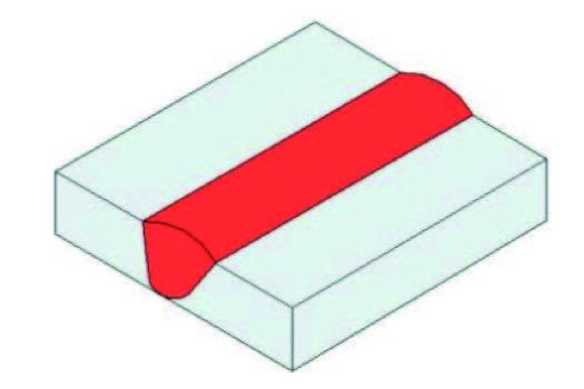
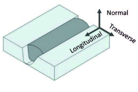
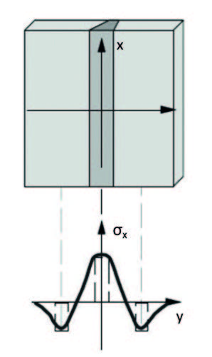
Arc welding processes – GMAW, GTAW, SMAW, – involve fusion of materials, and that means a fast, localized, and nonuniform variation in temperature. When metals are heated, they expand; if they are left to cool, they contract. However, the metal in a weld joint is not free to move; that leads to the rise of residual stresses along the weld (longitudinal), across the weld (transverse), and through the weld (normal), as can be seen in Figure 1.
If left unchecked, residual stresses and deformations might affect the usefulness and dimensional stability of the welded part. The rise of residual stresses in welded joints can create several problems, such as crack formation, and a higher susceptibility to material fatigue, corrosion, and brittle fracture.
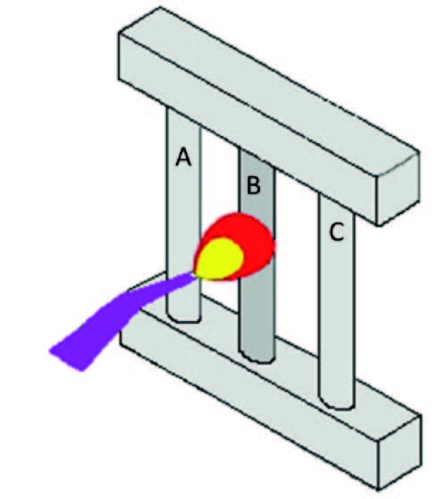
Another way of visualizing how residual stresses are created is to imagine a weld joint as an assembly of bars, as shown in Figure 2a. At room temperature, there is no internal stresses in any of the bars that compose the assembly. Now, suppose only bar B is heated by an oxy-acetylene torch. At first, restricted thermal expansion causes compressive stresses in bar B and tensile stresses in bars A and C.
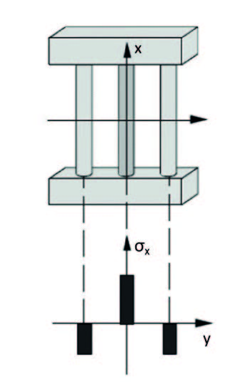
As the temperature rises, bar B begins to deform; first elastically and then plastically. When the heating stops, bar B begins to cool and contracts, reducing the compression effort, until it becomes null. As the temperature keeps dropping, bar B now starts to become subjected to tensile stress, while bars A and C become subject to compression stresses (Figure 2b).
In a weld joint, bar B is the equivalent of the weld bead and bars A and C are the base metal (Figure 2c). The weld bead develops tensile residual stresses, and the adjacent base metal develops compressive residual stresses.
Factors Affecting Weld Distortion
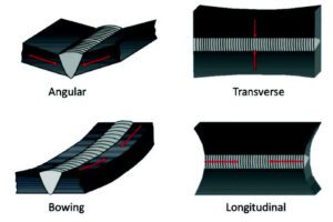
Distortion, or warping, is undesired deformation; a change in the original joint design caused by residual stresses. As residual stresses are an inherent part of arc welding, it is fair to say that all weld joints will present some degree of distortion. Figure 3 shows four of the main types of distortion associated with welding. Aside from the types shown in Figure 3, there is also rotational distortion (when the gap between the pieces changes as the weld progresses) and buckling (when bowing alternates direction along the weld).
The factors that affect weld distortion can be divided in three main categories: Structural Parameters, Manufacturing Parameters, and Base Material Properties.1 Structural Parameters include plate thickness, weld groove geometry and joint type. Fabricators usually do not get to choose plate thickness – this value comes from design calculations – but thicker plates tend to increase structural rigidity, reducing the final weld distortion. On the other hand, weld groove geometry and joint type can be selected – and they have great influence on distortion.
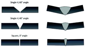
As a rule of thumb, the less weld metal you add and the more you balance the thermal stresses through plate thickness, the less distortion you get. That means that a double-V joint distorts less than a single-V joint; and that a single pass using a narrow groove will also distort less than a typical single-V, multipass, joint (See Figure 4).
The effect of ‘Manufacturing Parameters’ on distortion are related to welding parameters and procedures. A combination of both that would render the least amount of distortion would be a mechanized welding process, with a concentrated heat source, able to achieve high travel speeds, deep penetration, and capable of filling the joint with minimum amounts of weld runs and weld metal.
Finally, there are Base Material Properties; this is the group that makes a big difference whether welding stainless steels or carbon steels. There are four properties that influence distortion; two are mechanical properties and two are physical properties. They are defined below, and Table 1 presents values for three common types of steels.
Modulus of elasticity – also known as Young’s modulus, it is a measure of the stiffness of an elastic material – how easily it can stretch and deform- and it is defined as the ratio of stress to strain. A higher modulus of elasticity means a more distortion-resistant material.
Yield strength – Indicates how soon permanent deformation occurs. It is the stress at which a material begins to yield and deform plastically. “As the yield strength goes up so does distortion susceptibility. This is because after the stretching and contracting caused by the thermal cycle induced by welding, the material is stressed to approximately its yield strength. The higher the yield strength, the higher the residual stress that will act to distort the material.” 2
Coefficient of thermal expansion – defines the rate at which a material expands (or contracts) with an increase (or decrease) in temperature. The higher the value, the more a material is going to change in volume. Therefore, materials with a high coefficient of thermal expansion are more susceptible to distortion.
Thermal conductivity – tells us how good a material is at conducting heat. The higher the number, the better heat flows through the material and dissipates. If thermal conductivity is low, like in stainless steels, there is more chance of distortion, due to a more pronounced temperature gradient.
Comparing the values on Table 1, one can see that Carbon Steel (CS), Stainless Steel (SS), and Duplex Stainless Steel (DSS) have similar modulus of elasticity. So, this property alone is not very helpful in predicting distortion. For the steels on Table 1, predicting distortion requires a combined view of the remaining properties. For example, DSS has a yield strength that is almost the double of CS and SS. The coefficient of thermal expansion is also higher than CS and the thermal conductivity is about a third of CS. So, that means that distortion is much more likely to happen in DSS than in CS. As for SS, distortion is also more likely to happen than in CS, due to the higher coefficient of thermal expansion and lower thermal conductivity. This a very basic analysis, for there are also other parameters that may influence distortion, such as phase transitions on base and weld metal, which can be associated with volume changes.
How To Deal With Distortion
As we have seen, weld and distortion walk hand in hand. As long as you have a localized, steep gradient in temperature, metals will tend to distort. For stainless steels, their mechanical and physical properties make them especially prone to distortion. If there is no way to eliminate distortion, at least there are ways to control it. Below you will fi nd some of the common techniques to minimize distortion.
1) Use the least amount of weld – The more metal that is added to a joint, the thicker the bar B (see Figure 2) and, consequently, the greater the shrinkage forces. So, correctly designing and executing welds to deposit the minimum amount of metal not only reduces distortion, but also reduces costs (electrodes and time). “The amount of weld metal in a fillet weld can be minimized by the use of a flat or slightly convex bead, and in a butt joint by proper edge preparation and fitup. The excess weld metal in a highly convex bead does not increase the allowable strength in code work, but it does increase shrinkage forces.”3 If the design allows, use of intermittent welds instead of continuous welds is a also a possibility for reducing the amount of weld metal.
2) Use as few weld passes as possible – Filling the same volume with fewer weld passes reduces shrinkage stresses and angular distortion, as the shrinkage effect of each pass is cumulative. So, by using larger electrodes – instead of many passes with thinner electrodes –is possible to reduce total distortion.
3) Weld on or near the neutral axis – According to the AWS, the neutral axis is “The plane of a material, usually along its geometric center, where it experiences no natural tensile or compressive forces.”4 By placing welds on or near the neutral axis, “distortion is minimized by providing a smaller leverage for the shrinkage forces to pull the plates out of alignment.” 3 See Figure 5 for a better understand of the concept.
4) Balancing the welds around the neutral axis – Using symmetric joint designs (double-V or U instead of single V or U) helps reduce distortion. Better yet if welds are applied in a balanced way around the neutral axis of the structure, as seen in Figure 6. Figure 6a shows a symmetric joint design but with a non-optimum weld sequence, resulting in significant angular distortion. Figure 6b shows a better sequence where the shrinkage stresses produced by one weld is balanced by the shrinkage stresses produced by another weld across the neutral axis.
5) Anticipating shrinkage forces with presetting – Presetting is about positioning the pieces to be welded in such a way that the shrinkage forces are accounted for, and the final result shows no distortion.


Conclusion
Residual stresses generated by arc welding tend to cause distortion if the material is free to move. If restrained, such as by the use of clamps, distortion may be low, but residual stresses will be higher. That may initiate cracks and lead to an earlier failure while in service.
Controlling distortion usually incurs in a higher weld cost. For example, double-V joints with balanced welds reduce distortion, but require more preparation and intermediary steps during welding. As such, the joint designer must fi nd a compromise between controlling distortion and keeping costs down.
References
1. Cordeiro, F. D. S., A Critical Analysis on Weld’s Distortion, Dissertation submitted in Partial Fulfilment of the Requirements for the Degree of Master in Mechanical Engineering in the specialty of Production and Project, Universidade de Coimbra, 2015. Available at https://estudogeral.sib.uc.pt/bitstream/10316/38969/1/A%20 Critical%20Analysis%20on%20Weld%20s%20Distortion.pdf
2. https://weldinganswers.com/4-material-properties-that-affect-distortion/
3. https://www.lincolnelectric.com/fr-fr/support/welding-how-to/Pages/weld-distortion-detail.aspx
4. https://awo.aws.org/glossary/neutral-axis/


