The objective of cathodic protection (CP) designing is to obtain pipe-to-soil potential along the entire length of a pipeline within the limits of the protection criteria. In CP designing, many characteristics and parameters are measured, and theoretical calculations are conducted in order to design systems with optimized protection.
Data collection, pre-design surveys, current design calculations, CP circuit designing, and pipeline attenuation calculations are the main parts of designing something that looks simple but sometimes becomes complicated due to unusual challenges. Some of these challenges include different geographical conditions, existing pipelines in common corridors, electrical continuity with incidental structures, earthing systems, and alternating current/direction current (AC/ DC) interferences. In this paper, these challenges and their associated problems are addressed with potential solutions.
CP design challenges
Electrical isolation in multiple pipelines corridors
The loss of a CP current due to metallic contacts between the pipeline and other structures is a concern. The incidental metallic contacts cause the low potentials on pipelines, and adds an extra load on CP systems, which then results in a larger surface area to protect. Therefore, electrical isolation of the pipelines is mandatory at all underground and above-grade transition points including plants, terminals, pump stations, valve stations, etc.; essentially, wherever the possibilities of electrical contact with earthing systems can be foreseen. Earthing systems that consist of bare galvanized steel or copper conductors are able to draw most of the CP current.
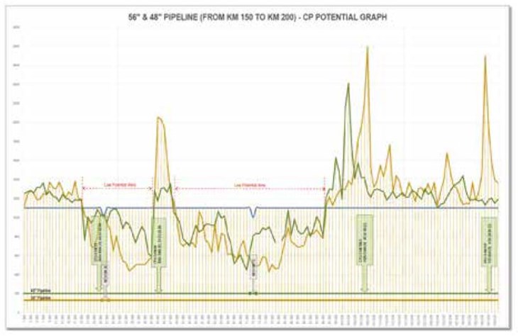
Generally, pipelines are isolated through isolation flange kits and monolithic isolation joints. This condition becomes challenging in corridors of multiple pipelines. This is where all pipelines are bonded together as per the standard regulations, and some of the pipelines in these corridors have experienced failed, or no isolation at all. There are existing cases that have resulted in CP current losses and low potentials. Figure 1 shows similar cases where all pipeline potentials are low due to the electrical continuity of pipelines in a valve station piping and earthing system, as well as coating damage.
In such cases where effective electrical isolation for the pipelines cannot be achieved, a few approaches can be applied to resolve the problems.
1. Design and locate CP source units away from the earthing systems in such a way that the CP current path towards grounding becomes highly resistive in comparison to the current path towards pipelines.
2. Design supplementary CP for associated structures based on earth-rise potential method. This approach is being used to design a CP system with a remote anode groundbed for pipelines and a distributed anode groundbed for valve station piping and grounding, with a single CP source unit. The current distribution between these two anode groundbeds is controlled through cable sizes and lengths.
3. Design a supplementary CP system in plants and valve stations where pipelines are connected with piping and other structures. Lay linear anodes along the pipeline and piping with a dedicated CP source unit.
4. The installation and repairing of insulation kits for existing pipelines may be an effective solution during a shut down. In this case, all electrical isolation points must be provided with safety devices like spark gaps or DC decouplers.
5. Installation of DC decoupler devices or earthing cells at valve stations can make also grounding an effective solution in case of less numbers of earthing connections.
Attenuation in multiple pipelines corridors
Pipeline attenuation calculation is one of the most important steps of CP designing because it determines the extent of electrical losses along the structure. The quantities and distances of CP source units are determined based on the attenuation calculation results.
The attenuation calculation is based on two important factors: pipeline lineal resistance, and coating leakage conductance. Pipeline lineal resistance is the function of electrical losses due to pipeline base metal, which is dependent on the dimensions, thickness and material resistivity. Pipeline leakage conductance is the function of electrical losses due to pipeline-to-ground interface conductance, which is dependent on dielectric strength of pipeline coating and electrolyte conductivity. If the pipeline coating is new and in good condition, then the dielectric strength is high and attenuation is low, whereas it is reversed in the case of an old and poor-coating conditioned pipeline. Hence, attenuation is mainly based on the condition of the pipeline coating.
The cases where a new pipeline is to be installed in a corridor of existing pipelines with old and poor coating conditions, then the attenuation calculation will not be as simple as for a newly-coated pipeline. In this case, the two following approaches can be utilized.
1. In theoretical calculation, all variable and parameters are to be considered as worst case. For example, in a group of pipelines in a corridor the smallest diameter pipeline should be considered for calculation, coating conductance value will be considered for oldest pipelines, and lowest value from the measured soil resistivity should be taken into consideration to have the most conservative results.
2. Measure the CP source coverage individually over the pipelines during the pre-design survey. This will provide an extensive amount of information needed for CP in the local environment. Evaluate from the CP monitoring data of existing pipelines, which will show the extent of CP in local environment.
3. Coating rehabilitation of existing pipelines is important in order to reduce the overall CP current demand, lower the attenuation, and optimize the CP protection levels.
The locations and designing for anode groundbeds
The performance of an anode groundbed is dependent on several factors such as location, type, designing, resistivity, subsoil strata, material quality, installation practice, and ventilation systems. Design challenges related to
these factors are discussed in this section.
Generally, anode groundbeds in high-resistive environments are unable to impress the same amount of a current as those in low-resistive environments. Therefore, most groundbeds are designed in low resistivity environments for higher current outputs. A disadvantage of low-resistive anode groundbeds is that it cannot force the CP current in high-resistive environments if the same structure passes through different environments. Therefore, in multiple environment conditions the anode groundbeds need to be designed for high-resistive soils. In order to lower the groundbed-to-earth resistance different approaches can be used, such as designing multiple anode groundbeds in parallel or designing anode groundbeds with a watering system.
There is a case observed during commissioning of a newly-installed system where a surface anode groundbed in a high resistivity environment cannot impress the CP current more than 2km on the pipelines. After re-designing with a deep anode groundbed, the same system resulted to impress the CP current more than 10km on the pipelines.
The performance of the anode groundbed is measured to provide optimum current output until the designed lifetime, therefore quality control and inspection of the anode groundbed material is important. The quality hold points are anode material, anode-to-cable connection, cable insulation, a coke breeze, and a proper ventilation system.
CP circuits complications
CP circuit calculations are conducted to evaluate the overall CP circuit resistance, and ensure it is balanced within the capacity of the CP source unit resistance. The purpose is to ensure that the CP source unit operating parameter will remain within the rated capacity. During this calculation the resistance of each contributing factor is calculated and added in circuit like groundbed-to-earth resistance, anodes cable tail resistance, positive header cable resistance, negative header cable resistance, negative distribution cable resistance, cathode resistance, and back electromotive force (EMF) resistance due to cathode-anode potential differences.
A CP circuit design, whether for a new system or modifications of an existing system, can become complicated due to the addition of many variables and factors. These factors can include the addition/ deletion of anode groundbeds, addition/deletion of a pipelines, and relocation of the anode groundbeds. For existing system modifications, field measurements are required.
In new CP circuit design methods, Electrical Circuit Modeling and Simulation (ECMS) software are not only used to validate the CP circuit calculations but to also simulate the current distribution in the circuit. Through these simulations the CP current distribution can be evaluated and, by applying modifications, can also be controlled.
In an experienced case, supplementary CP of a valve station piping based on distributed anode groundbeds was the main part of a CP circuit with a remote anode groundbed for pipelines. Initially this system was working to distribute 40% of its current toward a deep anode groundbed, and 60% of its current towards a distributed anode groundbed. This distribution impacted as low potential on a main pipeline, and very high potentials on the valve station piping. With small modifications of the cable’s size and length, the current distribution was changed to 70% going toward the deep anode groundbed, and 30% toward the distributed anode groundbeds.
Similarly, the current distribution between the pipelines can be controlled through the resistance in the negative return path. In such cases, the current is controlled by adjusting the cable’s size and length in a negative loop of the circuit. For optimum results, field tests are required to measure each individual pipeline-to-earth resistance, seeing as the results may vary due to the dimensions and coating conditions of each individual pipeline.
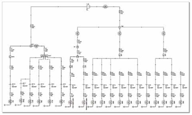
Simulating a CP circuit before installing the system can significantly improve the design efficiency, as well as save time during the installation phase. Figure 2 shows an example of ECMS modelling of a CP system with two different anode groundbed systems.
Overhead power transmission lines
Pipelines under the influence of an AC interference due to a nearby high-voltage alternating current (HVAC) overhead transmission lines, are usually associated with two types of hazards. First is an electric shock hazard for the people who may be, or might come in contact with abovegrade metallic connections of underground pipelines, or exposed to a step potential hazard. The second is AC corrosion on the pipelines itself.
Pipelines with suspected AC hazards should be evaluated to identify the quantum of AC-induced voltages and the level of an AC interference, as well as to provide mitigation design in order to eliminate all risks associated with AC hazards. These evaluations are usually done by field measurements and AC interference simulation software. In this study, the following investigations are conducted.
1. Personal safety under steady state and fault conditions.
2. Pipeline coating damage under fault conditions.
3. Pipeline AC corrosion under steady state conditions.
4. Arcing between HVAC tower grounding and pipeline under fault and lightning conditions.
To mitigate the excessive AC current density and coating stress voltage on pipelines, the mitigation system usually consists of bare grounding wires, connected with a pipeline through DC decoupler devices. Further grounding mats are used at all above-grade connections points in close vicinity of HVAC transmission lines. There are special types of CP test stations that provide protection from AC shock called, Dead Front Test Stations, with grounding mats.
Helping the design community
This paper discusses the general design practices, new design approaches, challenges being faced by the CP system designers and operators. It provides a summarized idea about possible and practical solutions based on the authors’ experiences in designing and maintaining CP systems. The authors have earnest hope that their efforts, which are the result of practical verification of application of their design challenges solutions, will be found useful and will serve the design community well.
References
1. NACE SP-0169 Control of external corrosion on underground or submerged metallic piping system
2. NACE TM-0497 Measurement techniques related to criteria for cathodic protection on underground or submerged metallic piping system
3. Cathodic Protection Design Considerations for New Pipelines in Existing Pipelines Corridor (Pankaj Panchal, Faiyaz Ahmad)
4. Innovative Design for Deep well Anode bed in High Resistivity Area (Pankaj Panchal, Faiyaz Ahmed)
5. Design and optimization of pipeline cathodic protection systems (Marius Purcar, Leslie Bortles)
About the authors
Qurban Ali Lashari is a Corrosion Engineer associated with the Northern Area Pipeline Department of Saudi Aramco. He is a National Association of Corrosion Engineers- (NACE) certified Senior Corrosion Technologist, with more than 27 years of experience in corrosion control, coating, corrosion inhibitor management, and cathodic protection. Also a certified technical trainer, Lashari has conducted many international trainings around the globe.


