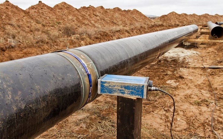
The CP designing process
CP designing for pipelines starts with a comprehensive pre-design survey where required measurements and assessments of all variables are gathered in the field. Data collection and survey requirements If a new pipeline is being laid in an independent corridor, the methodology of data collection and survey requirements will be as followed:
1. Pipeline data, such as diameter, length, wall thickness, base metal, coating type, burial depth, valve stations, under- ground/above-ground (UG/AG) transition points, etc.
2. Assessment of soil conditions, and the resistivity measurement along the entire length of the pipeline and the proposed anode ground-bed locations.
3. Electrical isolation of the pipeline at UG/AG transition points, along with other structures in case electrical contact is a possibility.
4. Parallel and crossed pipelines data; for example, location, distance and length of parallelism, location of crossings, and potential measurements.
5. Road, railway and river crossings, casings used in crossings and types of crossings like open cut, thrust bored, micro tunneling, horizontal directional drilling etc.
6. High-voltage power lines (HVPL), parallelism, and crossings. This requires extensive data collection at the site and from the power generation house to perform AC mitigation studies, as required.
In the case of a new pipeline being laid in an existing pipeline’s corridor, then the data collection and survey requirements are expanded with the following additional requirements:
1. The existing pipeline’s data, such as diameter, length, wall thickness, base metal, coating type and condition, burial depth, valve stations, UG/AG transition points, etc.
2. The distance between each pipeline (edge to edge).
3. DC/AC potential measurements of existing pipelines.
4. Operating and rated outputs of CP source units nearby, which are connected to existing pipelines.
5. Distances and operating outputs of anodes and anode ground-beds of CP source units nearby, as well as connected to existing pipelines.
6. Any data related to existing pipelines coating conditions, integrity assessments and rehabilitation/repairs will be additive to evaluate the existing conditions and critical locations.
7. Bonding details and current measurements at each bond station and its direction.
8. Earthing system details, especially the method and location of grounding.
Pipeline casing details at road/railway crossing; for example, the type of casing, its isolation method, coating details, present isolation status.
The data related to the pre-design survey determines the factors such as soil resistivity, the type of anode ground-bed required, location, and capacity of CP source units, AC power availability and its KV ratings, location of electrical bonding, location of monitoring facilities, requirement of bonding facilities, supplementary CP requirements, different types of crossing details (road, pipeline and HVPL etc.), existing CP system operating parameters, AC induced voltages, AC current densities, interferences mitigation requirements, and over voltage protection requirements.

Designing
The next step is to perform the CP design through electrical and mathematical formulas, which comprise the CP current requirement calculations based on the established current densities for the known environment and coating types, CP source unit sizing calculations, anodes/groundbeds calculations, CP circuit resistance calculations, earth potential rise calculations, pipeline attenuation calculations and system life calculations, and AC mitigation requirements, if required.
When designing a CP system using galvanic anodes, the main basic requirement is to calculate the pipeline’s current requirement and required number of anodes by mass and current. Based on theoretical calculations for coated structures and an average, dry environment, the required anode quantities are computed as low, however, there should be considerations for environmental changes and seasonal effects such as rain, temperature changes, coating degradation, natural heterogeneity and fluctuations in ground water levels causing variation in soil resistivity. Therefore, the proposed anodes quantities should be more than the computed depending on expert judgments and past experiences in similar areas.
While designing a CP with an impressed current cathodic protection (ICCP) system, the main basic requirements are to calculate the pipeline’s current requirement, the anode bed sizing, CP circuit resistance, sizing the power source, and the pipeline attenuation calculation, to see the CP current spread over the structure. These are all based on theoretical calculations; however this can effectively determine the limits of operations based on considered worst-case design parameters.
CP design challenges
Various geographical environments
One big challenge that needs to be taken into consideration is the different environments pipelines can face. In North America alone, various states and provinces experience extreme weather involving snow, rain, extreme heat and winds, and that is not even including other corrosion-threatening variables such as salt, sand, and rocks. Each condition and variable will offer different levels of corrosion resistivity:
1. Coastlines where high salt contents are present in-ground due to coastal sediments and groundwater sediments, there is risk of extremely low resistivity.
2. Desert-like areas with low salt contents but consist of sand have considerably high resistivity.
3. Areas consisting of rocks and mountains where formation is extremely dry and hard, pipelines are laid in trenches filled with soil and sand from other areas, therefore creating high resistance in surrounding.
4. Low altitude areas with heavy rainfall experience will often experience displacement of soil around pipelines.
5. Agricultural areas are the lands used for cultivation. These areas consist of loams where resistivity is low.
CP designing for these pipelines which are passing through different areas is always a challenge due to following reasons:

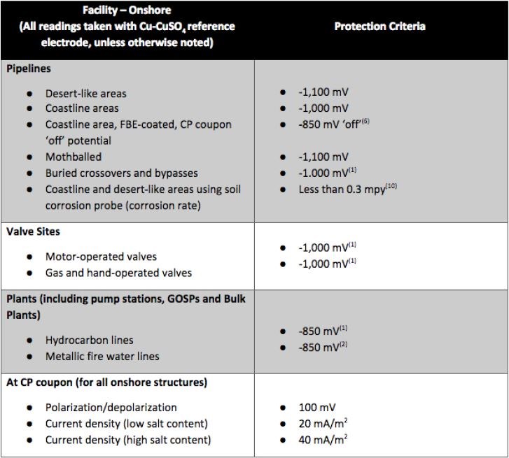
• Potential criteria for protection might vary due to the environment around the pipeline surface, therefore, defining minimum and maximum limits of protection criteria is critical. Various companies have conducted studies on pipeline corridors and established protection criteria for their pipelines in different environments. Figure 1 is a local company’s standard criteria, for the potential ranges in various environments and structures. Another approach while designing is to select a few representative locations of different environments based on a soil resistivity survey along the pipeline, and propose to install test stations with coupons for the evaluation of true polarized potentials, IR drop in soil and protective current densities during commissioning.

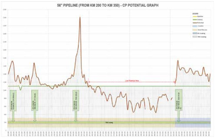
• CP current distribution on a pipeline in different environments is affected as current flows through the lowest resistance path. A CP current cannot be forced to flow from a low resistivity area to a high one, ultimately leaving the portion of the pipeline in the high resistivity area, with an inadequate CP current. Figure 2 shows a condition of a pipeline in a coastline area, and a desert-like area, where the CP source unit is in a coastline area. The immediate potential drops in the desert-like area shows the low current distribution towards this area. The best way to counter this problem is to design a CP source unit in high resistivity areas.

• The rocky and mountainous areas are generally very hard and dry, which cause CP current shielding on pipeline surfaces. The external corrosion rates in these areas are extremely low. However, during long periods of heavy rainfall, this can be critical for the pipelines that have been laid in the trenches filled with foreign soils, which get damped and cause acceleration to the corrosion rate. Figure 3 shows an exposed pipeline in a trench in a rocky area. Here, supplementary protection with galvanic anodes or galvanic ribbons can be effective to provide localized CP protection. An ICCP system with linear anodes can also be an option in case of CP source units installed with effective intervals based on a linear anode’s current attenuation.

• Washouts around the pipelines are very common in areas with extreme rainfall. This causes portions of the pipe to surface, which is why these pipelines are encased in concrete to protect from the damages caused by fallen stones and rocks. These portions of the pipeline are subject to CP current shielding. For exposed pipeline surfaces, CP cannot be the solution for protection, therefore extra coating must be applied to the pipelines in these areas. Figure 4 which shows the exposed pipeline due to soil displacement.
References
1. NACE SP-0169 Control of external corrosion on underground or submerged metallic piping system.
2. NACE TM-0497 Measurement techniques related to criteria for cathodic protection on underground or submerged metallic piping system.
3. Cathodic Protection Design Considerations for New Pipelines in Existing Pipelines Corridor (Pankaj Panchal, Faiyaz Ahmad)
4. Innovative Design for Deep well Anode bed in High Resistivity Area (Pankaj Panchal, Faiyaz Ahmed)
5. Design and optimization of pipeline cathodic protection systems (Marius Purcar, Leslie Bortles)
About the authors
Qurban Ali Lashari is a Corrosion Engineer associated with the Northern Area Pipeline Department of Saudi Aramco. He is a National Association of Corrosion Engineers- (NACE) certified Senior Corrosion Technologist, with more than 27 years of experience in corrosion control, coating, corrosion inhibitor management, and cathodic protection. Also a certified technical trainer, Lashari has conducted many international trainings around the globe.

Muhammad A. Sherwani is a Corrosion Engineer in the East West Pipeline Department of Saudi Aramco. He is a NACE-certified Corrosion Specialist and Cathodic Protection Specialist, with 18 years of experience in pipelines corrosion management and cathodic protection system designing.

Feature image courtesy of Onshore Pipeline Engineering

