An insulated 4-inch 316L stainless steel pipe that leaked in hydrogen service was examined. The pipe was in 24/7 service, operating on alternate heating and cooling cycles. The process stream consisted of condensation hydrogen with traces of chlorosilanes. The objective of the lab analysis was to determine the cause of the leak. Visual examination, SEM microscopy, EDS analysis, metallography, and OES chemical analysis were performed. The results indicated that the pipe/elbow cracked from chloride-induced stress corrosion cracking that originated on the outside surface, likely caused by corrosion under insulation (CUI). Residual stresses from forming and welding contributed to the damage mechanism.
By Sudhakar Mahajanam, Vibha Zaman, MISTRAS Group, Inc.; Tyler Scherbarth, Fred Wade, Wacker Polysilicon North America, LLC
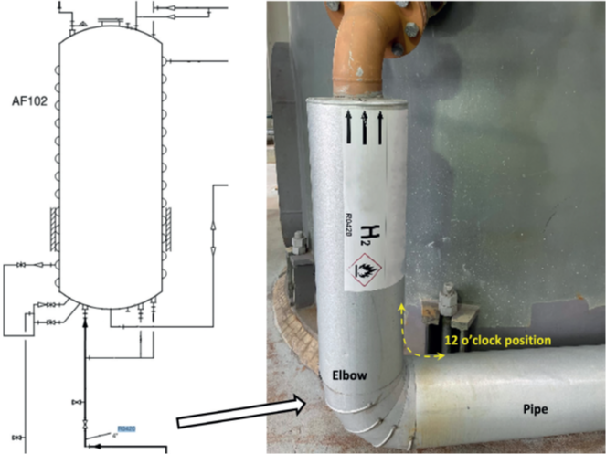
insulated 4-inch pipe/elbow in service.
Background
Stainless steels are utilized in a wide variety of industries, with austenitic stainless steels representing the largest group of stainless steels.1 However, in the presence of corrosive environments (such as aqueous chlorides or caustic solutions), tensile stress and elevated temperatures, austenitic stainless steels are susceptible to stress corrosion cracking (SCC).2
In this case study, failure analysis of an insulated 4-inch stainless steel pipe that leaked in hydrogen service was performed. The pipe is in 24/7 service, operating on alternate heating and cooling cycles (heating at 160°C, followed by heating at 210°C, then cooling to 25°C). The process stream of this inlet pipe consists of condensation hydrogen with traces of chlorosilanes, which is sent to the adsorber column as shown in the schematic and the photograph in Figure 1. The carbon in the column acts as an adsorber with steam being used to heat up the column and bake out the adsorbed chlorosilanes from the condensation hydrogen. The regenerated hydrogen is utilized in the production of silicones and hyper-pure polycrystalline silicon (polysilicon), which are used to manufacture electronics processors and photovoltaics for solar panels. It was reported that the process stream is dry and should not have any moisture present. However, the site did not rule out the possibility of moisture being present in the condensation hydrogen stream. Water is detrimental to the process, since it reacts with chlorosilanes to form HCl, which is highly corrosive to the equipment. The leak was found on the intrados side at the 12 o’clock position of the inlet pipe. It was speculated that the cracks likely formed prior to the leak, with high levels of hydrogen being detected by an operator using an air monitoring device.
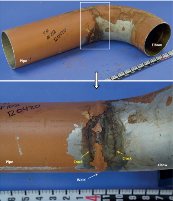
divisions are in inches.
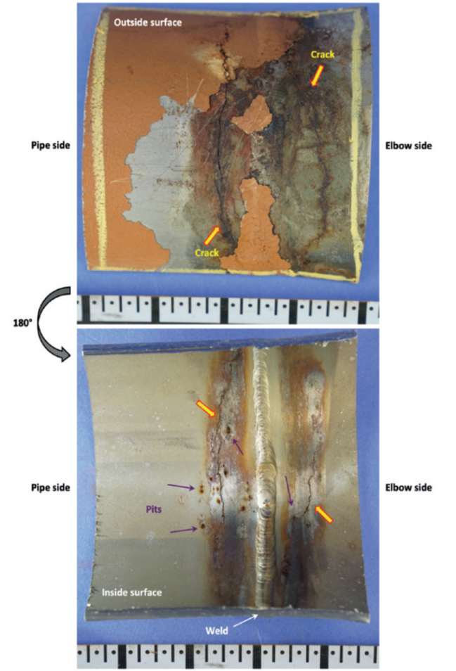
side of the weld. Major scale divisions are in inches.
Laboratory Examination
Visual Examination
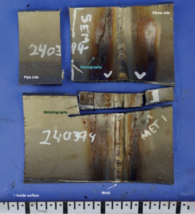
Figure 2 shows the as-received and close-up photographs of the pipe/elbow sample with the leak and crack locations marked. Two cracks were observed on either side of the weld between the pipe and the elbow on the intrados side. This region was sectioned, as shown in Figure 3. Several pits were observed on the inside surface close to the two cracks. The cracks were opened using lab overload for fracture surface examination.
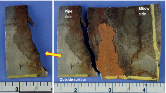
The sample segment containing the cracks was further sectioned for subsequent analyses. Figure 4 shows one section containing a crack on the pipe side that was selected for fractographic examination. Another section was prepared for metallographic examination. Close-up photographs of the region selected for fractography are shown in Figure 5 after lab break open. Figure 6 shows a stereomicrograph of the fracture surface. The fracture morphology appeared to be transgranular.
Scanning Electron Microscopy (SEM) and Energy Dispersive X-Ray Spectroscopy (EDS)
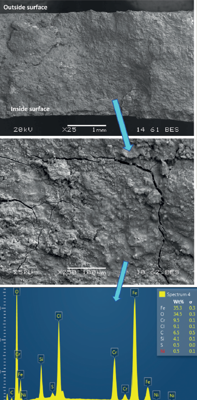
SEM and EDS analyses of the fracture surface were also performed, as shown in Figure 7. Deposits were observed on the fracture surface.
Standardless EDS analysis does not accurately measure carbon contents; hence, these values were excluded from the analysis. The deposits consisted of iron, oxygen, chromium, chlorine, and silicon along with traces of sulfur and nickel.
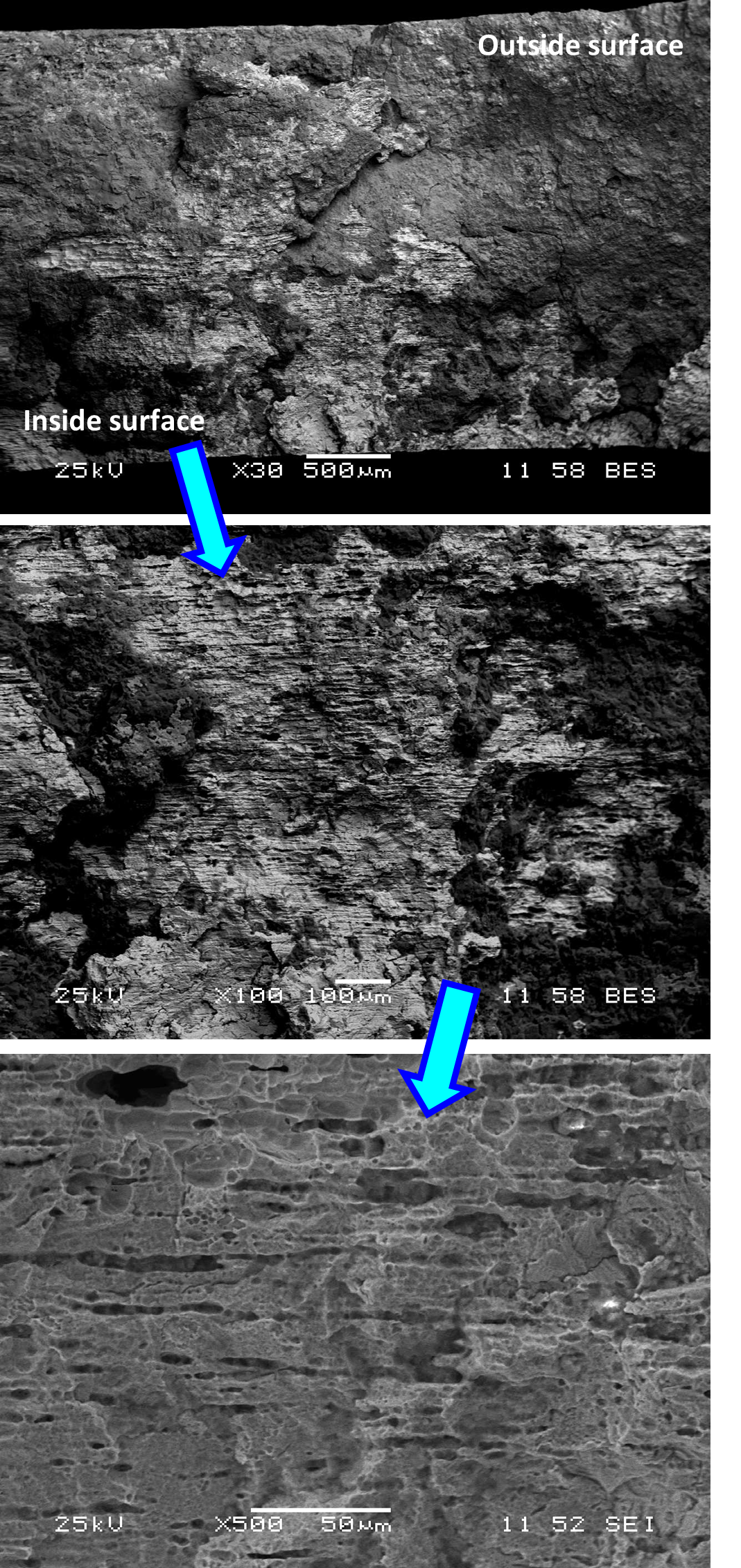
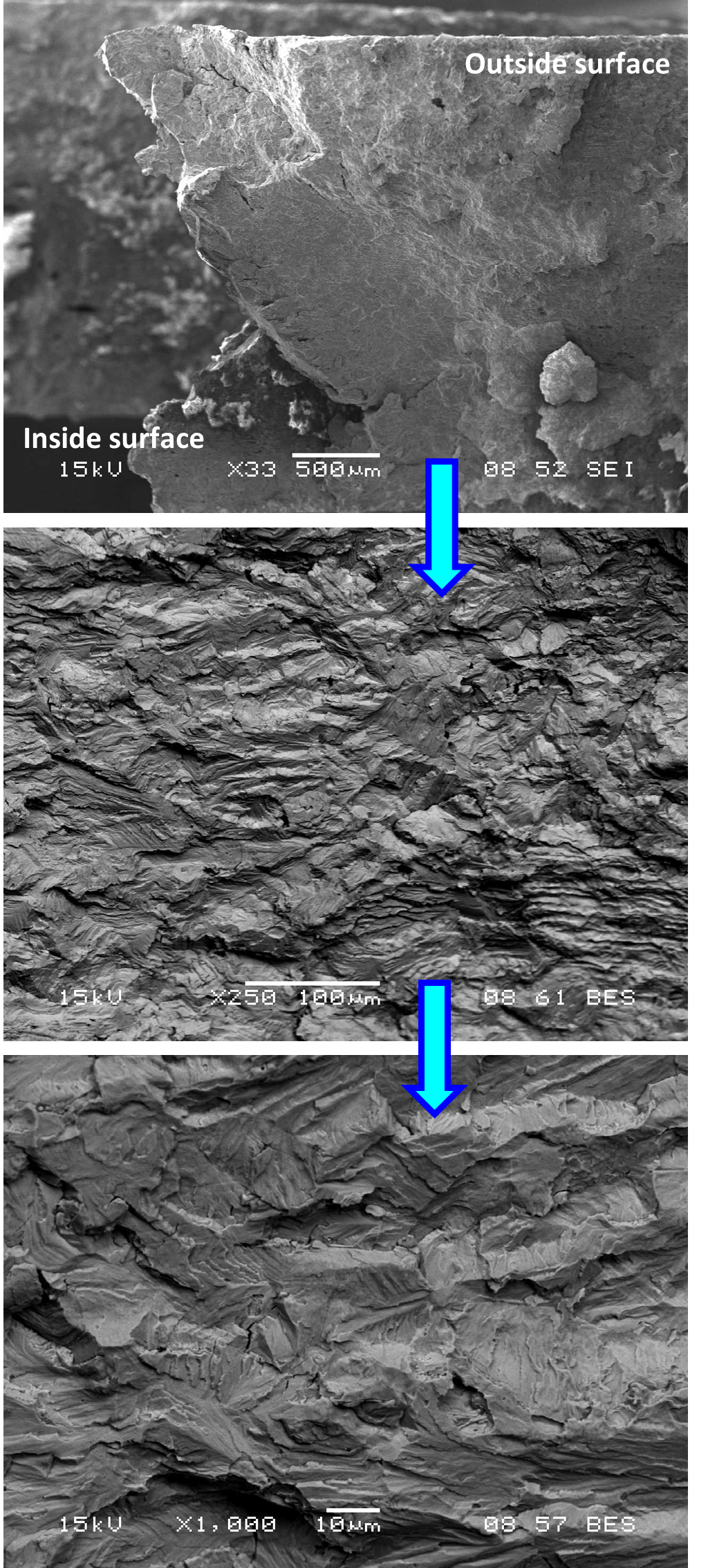
The fracture surface was cleaned ultrasonically, followed by SEM imaging, as shown in Figure 8. The fracture surface displayed several areas of pitting corrosion.
Figure 9 shows SEM images from another area of the fracture surface which contained no corrosion. The fracture morphology was transgranular with the cracking occurring by a cleavage mechanism.
Metallographic Examination
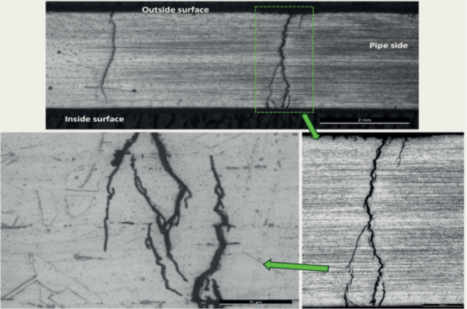
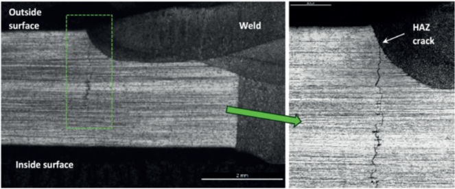
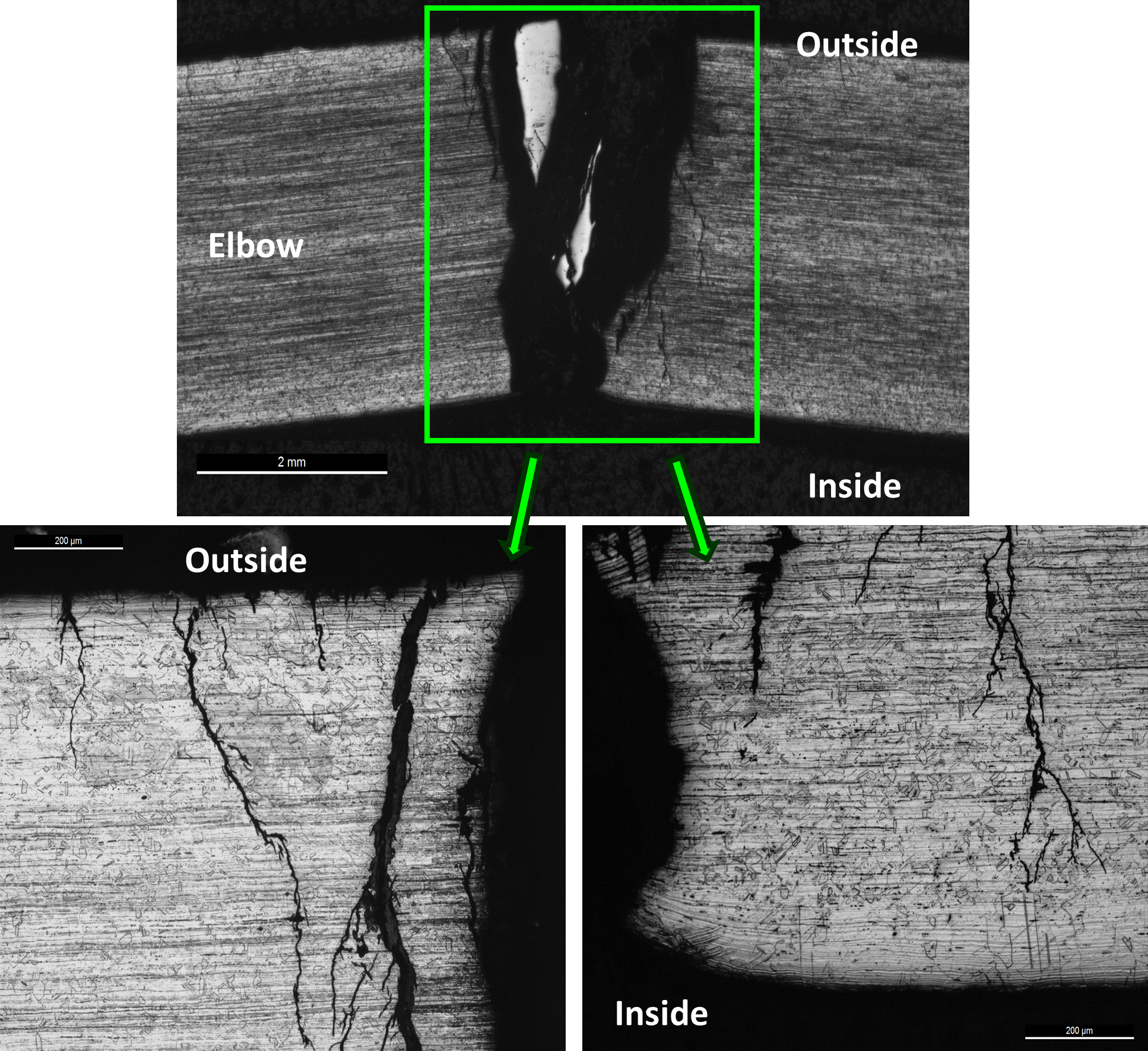
One metallographic mount was prepared using the section highlighted in Figure 4, shown again in Figure 10. The corresponding macrograph following metallographic mounting is also shown. Figure 11 shows the cracks on the pipe side of the sample; Figure 12 shows the cracks at the heat-affected zone (HAZ) of the weld on the pipe side; and Figure 13 shows the cracks on the elbow side of the sample. In all cases, the crack morphology was distinctly transgranular with the craze-cracked, lightning bolt appearance.

The cracks displayed multiple branching and originated from the outside surface of the sample. The microstructures of the pipe and elbow materials were typical of formed austenitic stainless steel, consisting of austenite grains along with bands of residual ferrite.
Microhardness Examination
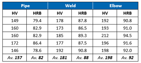
Vickers hardness (HV10) measurements were taken across the metallographic cross-section. The results shown in Table 1 indicated hardness values higher than the typical values of 79 HRB observed for UNS S31603 (316L) austenitic stainless steel.
Chemical Analysis
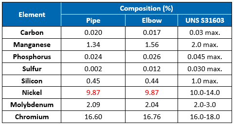
Chemical analysis was performed on the pipe and elbow sides of the sample using optical emission spectroscopy (OES). The results indicate that the chemical composition of the pipe and elbow was close to the requirements for UNS S31603 (316L) austenitic stainless steel (Table 2). The nickel contents were slightly below the 10.0% lower limit. However, it does not appear to have played a role in the cracking.
Conclusions and Recommendations
Based on the results of the laboratory examination, it is evident that the 4-inch pipe/elbow sample cracked from chloride-induced stress corrosion cracking (Cl-SCC). The cracks initiated on the outside surface, likely from corrosion under insulation (CUI). The fracture morphology was distinctly transgranular with branched cracking and cleavage facets being observed during SEM examination.
EDS analysis of the fracture surfaces confirmed the presence of chlorides, which promote Cl-SCC. The chlorides were likely present in the moisture that leached through the insulation and contacted the outside surface of the pipe at the 12 o’clock position. Residual stresses from the forming and welding processes associated with the pipe/elbow also contributed to the damage mechanism.
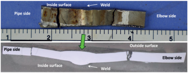
[Bottom] Macrograph showing sample cross-section.
Chemical analyses results for the pipe and elbow materials were close to the compositional requirements for UNS S31603 (316L) austenitic stainless steel. The general microstructures of the pipe and elbow materials were typical of formed austenitic stainless steel, consisting of austenite grains along with bands of residual ferrite. For 300 series SS, CUI and external Cl- SCC are possible when the equipment is operating between 60°C and 205°C.2 This damage mechanism occurs in the presence of water and oxygen and is accelerated when contaminants, such as chlorides, can concentrate or deposit onto the surfaces. In the case of insulated piping, condensation due to the temperature gradient or a break in the weather barrier causes water ingress, which is held in place by the insulation—thereby increasing the duration of wetting and the corrosion rate. CUI can be prevented by minimizing moisture accumulation between the insulation and piping through better design and use of caulking, by applying high quality barrier coatings, and by properly maintaining the insulation/ jacketing to mitigate against moisture intrusion.
